Testing a 13 Pin Towing Socket without a dedicated tester
diy electronics
Introduction
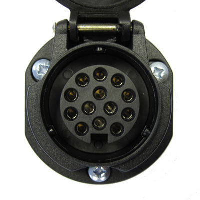
Recently I installed a 13-pin socket 1 on my car and I wanted to make sure all its functions are working correctly.
A 13 pin socket along basic brake, tail and indicator lights provides (as per the ISO 11446 standard) the rear fog lights, reverse lights, a permanent 12V connection and a switched 12V connection (when the engine is running or just the power being switched on in the car). So a bit more than the simpler 7-pin variant. Not to mention that fact that some sockets also disable the rear ultrasonic parking sensors when a trailer is connected.
These 13 pin sockets are (mostly) used for towing caravans since they need the permanent 12V connection for their accessories and use the switched connection for powering the fridge and charging a battery. They can also be used with trailers and tow-bar mounted bike racks that have fog and reverse lamps.
If you have a trailer with a 7-pin plug, there are adapters from 13 to 7 pins as well.
Owning none of the above and just having had the tow bar and 13 pin socket installed, I needed a way to check the socket was actually working according to spec (just for fun).
If you own a caravan you can test all the connections by actually connecting it and using it, but here are the alternatives in case you don’t:
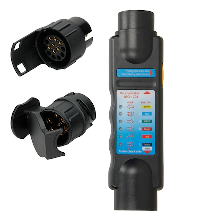
- Buying a dedicated 13 pin socket tester:
- Using a voltmeter and some light bulbs to simulate the caravan being connected.
I’m going to explore the second option, since it’s the fun and informative one.
Actually testing the socket
So we want to simulate the connection of a real trailer, but without the trailer, here’s how we do it.
Parts you’ll need:
- multimeter (we need the voltmeter)
- a 10W (minimum) bulb, I used a 21 Watt one
- wires
Warning: Make sure you’re not running your engine in an enclosed space, asphyxiation risk!
Warning: Make sure you’re not reversing with the engine running and a person checking the lights right behind the car, injury risk!
Warning: Make sure you’re not touching any live wires and to not touch them together, electrocution and fire risk! 2
Warning: Make sure you’re not invalidating any warranty for your car or tow bar by connecting stuff to it.
For reference, here’s the pin layout of the socket specified by ISO 11446 (courtesy of Wikipedia):
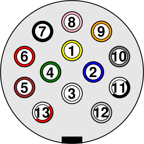
- Pin 1 - Left indicator
- Pin 2 - Rear fog lamp
- Pin 3 - Earth
- Pin 4 - Right indicator
- Pin 5 - Right tail lamp
- Pin 6 - Brake lamp
- Pin 7 - Left tail lamp
- Pin 8 - Reverse lamp
- Pin 9 - Permanent power
- Pin 10 - Switched supply (for fridge)
- Pin 11 - Earth for pin 10
- Pin 12 - Trailer Presence Detection / Unused
- Pin 13 - Earth for pin 9
So pin 3 is the ground pin for pins 1-8.
Pin 9 has its ground at pin 13 and pin 10 has ground at pin 11.
Usual functionality testing
Testing pins 1 through 8 is simple:
- Switch the voltmeter to 20V (or autoscaling) continuous current.
- Connect the ground of the voltmeter to pin 3.
- Signal a turn or press the brakes or turn on your lights and connect the red probe of the voltmeter to the equivalent pin of the tow bar socket.
- The voltmeter should read around 12 volts, maybe more, depending on your car battery.
If the voltmeter shows 0 or close to 0 volts, something is wrong. For the turn indicators, the voltmeter may not show exact readings since the voltage goes up and down with the signal, but it should change at the same rate.
Please note that for some of these to work you may have put your keys in the ignition and turn them to “ON”, for example the fog lights and the reverse lights need this.
Permanent power testing
This is simple: regardless of the state of your engine/ignition, connecting the voltmeter (set on max 20V) between pins 9 and 13 should read 12V or above.
Trailer detection
Depending on the socket and module you have installed pin 12 may or may not be the trailer detection pin, if it is, when connecting the trailer this pin will be connected to ground (pin 3).
On my particular installation (the MP5-DS-G13 module) the trailer detection is done by checking if a big enough load is connected between pin 6 and pin 3, which is equivalent to having working brakes on your trailer/caravan. Which makes more sense. If you have brake lights on your trailer, the system knows it’s connected, otherwise pin 12 might not be grounded with all trailer manufacturers. This is a cool trick and if I’m not mistaken provides compatibility even if you use a 13-7 pin adapter. This is cool since any trailer will have brake lights.
Now, make sure you connect a big enough load, I first connected a 5W bulb with nothing happening. After I switched to a 21W bulb the “trailer” was detected by the system.
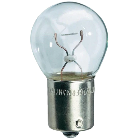
I used a car bulb from my spare set (which is mandatory to have in some European countries) to which I soldered a pair of wires to be able to plug them in the pins 6 and 3.
The rear parking sensors get disabled
If you connect this successfully and try to back up the car, your parking sensors will be switched off. This is useful since there is a permanent obstacle behind you and the sensors get annoying. Of course this doesn’t apply to adaptive parking sensors (which I hear can learn if there is a permanent obstacle and turn down the beeping).
Independent control of the car’s and the trailer’s fog lights
Also another cool feature of the module I got installed is that if I switch the fog lamps on and off I can control whether the fog lamps of the car and the trailer are on or only the fog lamps of the trailer. This is in order to avoid being blinded by the car’s fog lamp reflection off of the trailer. So:
- turn on: both car’s and trailer’s fog lamps are on;
- turn off: car’s lamps are off, trailer’s fog lamps are on - this avoid blinding you;
- turn on: both car’s and trailer’s fog lamps are on;
- turn off: both car’s and trailer’s fog lamps are off.
Switched power testing
This was the trickiest for me. According to many online sources pin 10 should come alive when the ignition is switched on or the engine is running. Well… this wasn’t the case.
Some sources say that the engine has to actually run for some time in order to charge the battery. Others say that you have to turn off you auto start/stop system.
It turns out these were all wrong for my module. The trick was the above trailer detection point. After I connected a 21 Watt bulb (as if there were a trailer connected) the fridge pin (10) came on and between it and pin 11 I had a potential difference reading of 12V on the voltmeter when the ignition was switched on. Success, all pins are working
Since the permanent power pin works even if a trailer is not connected. I somehow expected the switched power pin to work the same way. Just switch on the ignition and the pin should work, but I was wrong, a trailer has to be connected. This is what made me actually write this post, so that others will know to properly simulate a trailer connection.
-
I have the MP5-DS-G13 from quasarelectronics.pl - I’m not affiliated ↩︎
-
This is 12V, but better safe than sorry! ↩︎